NA Nodes
There are two types of NA Nodes, n/a and N/A and there are subtle differences between them that would help you identify the behavior of each when you see them on the IntraVUE Map View.
Auto Inserted n/a Nodes
Ethernet is a point to point protocol. An Ethernet cable can not be physically attached to more than one device at each end.
LAN traffic/packets move based on mac addresses
Switches move packets to ports based on mac address, Hubs move packets to all ports
Fully managed switches report mac addresses on each port
Anytime the scanner detects more than one mac address on the port of a managed switch that can not be resolved to a switch further down on that port, an auto-inserted node will be used to show more than one device on the port – only one line per port from the upper switch
Anytime only one mac is left on a port (because of a device move) the n/a node will be removed
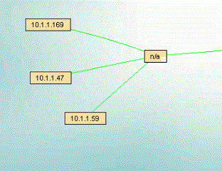
Lower case n/a nodes characteristics
Automatically inserted and removed by the scanner
Only appear on the port of a managed switch
Represents a device which causes the scanner to see more than one mac address on a port of a managed switch
Common examples:
-A hub
-An unmanaged switch (fails to meet RFC 1493 standard)
-A Wireless AP
-A Hypervisor Server
-A DRL Ring (daisy-chained or linear)
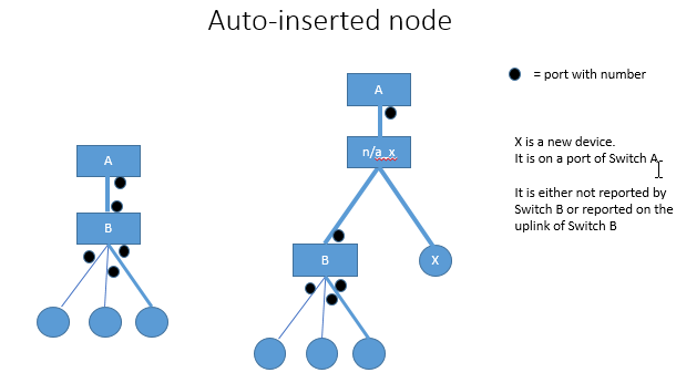
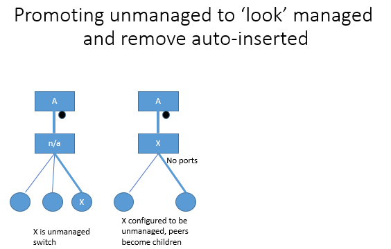
Search for "Device Configuration" and check the option "Virtual Machine, Unmanaged Switch" to device 'X' become the parent of the children in Map View that would replace that 'n/a' node.
Manually Inserted Nodes
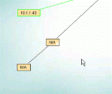
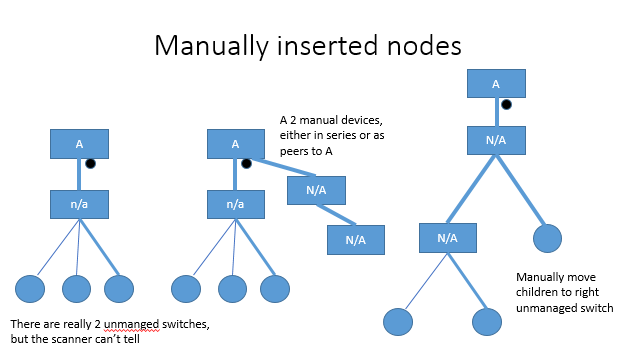
Upper case N/A nodes characteristics
Manually added by the user
May represent an unmanaged switch
Can show media conversion (copper to fiber and then fiber to copper)
Can show non-IP


