Creating Plant Documentation
Current device documentation does not reflect an up to date view of the plant network and a logical view makes it hard to keep up with relevant changes. These steps allow you to create current and relevant documentation for the IntraVUE plant network in logical format as well as in paper format.
-
Open a browser and go to http://127.0.0.1:8765. Change 127.0.0.1 to the address of the remote IntraVUE host as necessary.
- Click on any device. A slider bar will pop up on the right on the screen. This is your device properties panel.
![]() If you haven't Admin Verified such devices click "Admin Verify". See Admin Verification in IntraVUE 3
If you haven't Admin Verified such devices click "Admin Verify". See Admin Verification in IntraVUE 3
- Click "Edit".The Device Configuration dialog has 6 sections that allow you to configure the unique properties of a device.
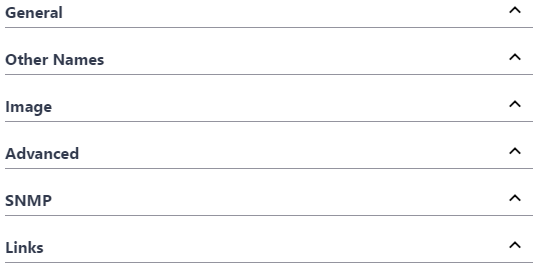
- In the General Tab > Set a defined device name and location.
- In the Other Names tab > Set additional defined names (i.e. function, description, owner ).
- In the Image tab > Assign an image from the drop down.
- In the Links tab > Fill in any documentation link (e.g. Administration Web link, Floor Layout, Maintenance user manual, wiring diagram, location pictures, various devices properties) for each URL NAME box that wasn't auto-detected by IntraVUE.
- Click " Apply and Close"
 Remember to save your changes before clicking on a different device as your changes will not be saved automatically.
- Continue doing this for all end devices, switches, and the top parents (i.e. router, IntraVUE™ agent, and the IntraVUE™ host).
![]() Refer to User-Defined Device Configuration for detailed explanations for all device properties
Refer to User-Defined Device Configuration for detailed explanations for all device properties
The Export / Import features are accessed from the Configure > Database Menu. This brings up a dialog which enables you to import data into or export data from IntraVUE.

Export
If you select the Export button, a standard Windows file download dialog will ask if you want to save the file or open it. If Microsoft Excel or similar spreadsheet program is installed, you may open the file directly into that. Export files are saved in plain text, comma separated value (CSV) format.
If you select the Choose... button next to Import, a standard Windows File Save dialog will presented. Navigate to the file you want to import and select it.
Import
If you select the Import button, the file listed in the filename field will start to be imported. Import files have to be in plain text, comma separated value (CSV) format.
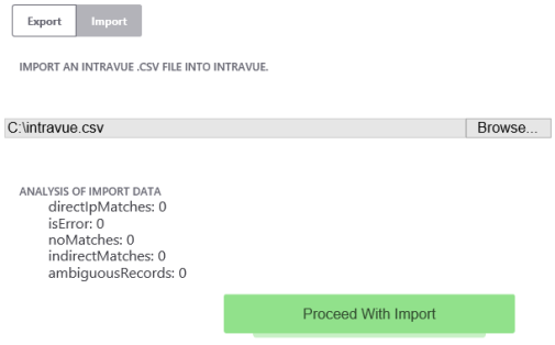
You must select the Proceed With Import button to complete the process.
Spreadsheet Notes
When you look at the exported data in a spreadsheet program you will find many columns. There are 3 basic sections:
- Reference data
- Configuration data for each IntraVUE™ 'View'
- Configuration data from the device's General Tab
- When saving the file, use CSV as the type and use quotes as the field marker. Don't use quotes in any view names.
Although the export function outputs many columns, you may delete columns you are not interested in EXCEPT the ipAddres, ref, and parentRef columns. These are used during the import process. You may not change any values to the left of DeviceName. They are shown in the image below.

See CSV Column Values for a list of available columns and values.
Refer to Export / Import for more options
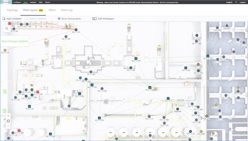
With this new feature you are able to manipulate the Topology view of your network to your individual requirements, draw individual zones or "containers" to re-arrange your network, and print the entire plant view with and without a background plant diagram or image in various ANSI sizes.
- Open a browser and go to http://127.0.0.1:8765. Change 127.0.0.1 to the address of the remote IntraVUE host as necessary.
-
Click "Plant Layout" and login as "admin"
- If you have a professional drawing image (*JPG, PNG, or GIF less than 10MB) click "Choose File" and browse to the location of image. To skip this step, click "Cancel" and go to # 5.
- Select a Size (ANSI Size A being the smallest and Size D the largest). Click "Submit".
- The Plant Layout has multiple Functions and Settings
- You can zoom in and out.
- You can move the entire topology to include areas outside of the screen area by doing a left-click hold with your mouse.
- You can move any node around 365 degrees by doing a left-click hold with your mouse and drag the node.
- To move a parent node and attached children without moving adjacent parents (and children) hold both the C-trl and 'x' keys and do a left-click hold with your mouse to draw an area around the devices you want to move. The area will disappear but the devices in the drawn area will be highlighted and ready to be dragged over to the desired location.
- To move a parent node and children including adjacent parents nodes (and children) click setting "Move Descendants" and simply left-click hold with you mouse to drag the parent node.
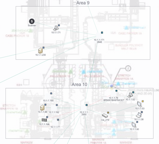
- To create custom areas that you can zoom in simply add containers. These are useful when indicating "zones" that reflect physical areas of your plant.
- Click "Add Container". Press and hold the Ctrl key and hold the left mouse button to draw a container zone with your mouse that surrounds a groups of nodes. You can move, expand, or shrink the area with your mouse. Subsequent areas will be numbered in sequence starting with "Area 1".
- You can zoom just that particular area by double-clicking on it.
- Click on a container (it will blue highlighted), and then click "Delete Container" to remove that area container.
- To add a background image of your plant floor or building site simply click "Edit Workspace".
If you have a professional drawing image (*JPG, PNG, or GIF less than 10MB) click "Choose File" and browse to the location of image
- Select a Size (ANSI Size A being the smallest and Size D the largest). Click "Submit".
- Uncheck "Add container" and leave "Move Descendants" checked to move parent nodes (see step 5 above).
- The Plant Layout view will be automatically saved to the IntraVUE system. A "New Changes Applied" banner in green letters will appear on the left side of the plant view confirming this. If you tab over to the Topology view and back you will notice the changes are saved.
- You can print the Plant Layout view using a screen shot tool (e.g. Snipping Tool, HyperSnap, Alt-PrtScn and Paint, etc) to a printer or plotter with these available ANSI size feed paper.
Size Width x Height (mm) Width x Height (in) Closest ISO ANSI A 216 x 279 mm 8.5 x 11 in A4 ANSI B 279 x 432 mm 11 x 17 in A3 ANSI C 432 x 559 mm 17 x 22 in A2 ANSI D 559 x 864 mm 22 x 34 in A1 ISO A0 841 x 1189 mm 33.1 x 46.8 in ISO A1 594 x 841 mm 23.4 x 33.1 in ANSI D ISO A2 420 x 594 mm 16.5 x 23.4 in ANSI C ISO A3 297 x 420 mm 11.7 x 16.5 in ANSI B ISO A4 210 x 297 mm 8.3 x 11.7 in ANSI A - You can also use the IntraVUE Plant Layout Export Tool (Available from Downloads )
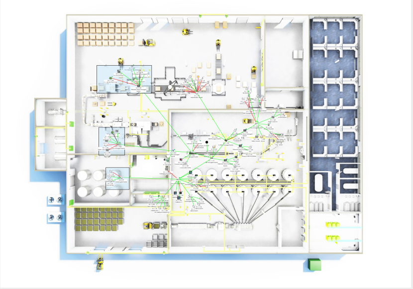
IntraVUE Network Layout Tool
The IntraVUE Network Layout tool allows your to create up to date documentation for the Ethernet plant floor by mapping an exported topology from IntraVUE onto a Visio drawing.
- Run "IntraVUE Network Layout - Beta.msi" program located here.
- The installation is self-explanatory (click "Next" and accept the defaults). If prompted by the windows User Account Control, accept "Yes".
- Open the IntraVUE Network Layout tool from Start > Programs > IntraVUE Network Layout - Beta 1.2
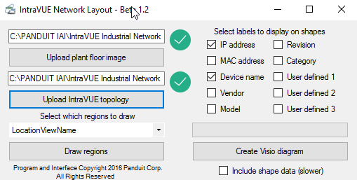
- Press "Upload plant floor image" button and select a background image to use for the diagram (i.e. a plant floor). You will be prompted to select a page size. You can choose from some standard sizes, or enter your own (in inches).
- Press "Upload IntraVUE topology" button and select a .CSV topology that was exported from IntraVUE.
To export a topology from IntraVUE, open up IntraVUE in your browser and login as Admin. Then, right-click anywhere
on the network and press "Export/Import" and press "Export" and save the file. This is your .CSV topology.
- Select a view from the dropdown which contains the regions you would like to draw (i.e. LocationView).
![]() A region's name is based on the Thumbnail .gif image. If you haven't selected a .gif image for that view, you will not see a region for that device or devices when this field is empty.
A region's name is based on the Thumbnail .gif image. If you haven't selected a .gif image for that view, you will not see a region for that device or devices when this field is empty.
- Press "Draw regions" button.
-
A Tools and Plant Layout window will appear.
-
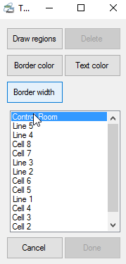
When the "Draw Regions" button is pressed, you will be able to click and drag on the plant layout to draw rectangles representing a region. The region is named based on the current highlighted name in the Tools window.
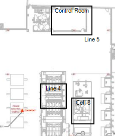
- You can continue to draw regions until you press "Done Drawing" and you do not have to draw all regions.
-
You can change the text color, border color, and border width of the region being drawn by pressing "Text color", "Border color", and "Border width" and making adjustments.
-
If you would like to delete a region, to either redraw or simply remove, make sure you are not drawing regions (by pressing "Done drawing" in the Tools window). You can press on any of the regions that have been draw to highlight them, and press on them again to unhighlight them. Then, press the "Delete" button in the Tools window to remove the highlighted regions from the diagram.
- Pressing "Cancel Tool" will cancel whichever tool you are currently using, such as the drawing tool.
-
Once you are finished with drawing any amount of regions, press the "Done" button in the Tools window.
-
- Check in the boxes that correspond to the labels you would like to appear on the shapes that are created within Visio.
-
Before pressing "Create Visio Diagram" you have the option to select "Include shape data (slower)" which includes more detailed information about each device in the background shape data. If you do not know what this means in Visio, then do not select it as it will only slow down the rendering process.
 You need Visio installed in order to successfully finish the next step and create a Visio drawing file *.vsd.
 - Press "Create Visio Diagram" button and pick a valid save location for the Visio diagram. Once completed, you will be prompted confirming where the diagram was saved.
- You may now locate the Visio diagram (.vsd file) and open it like any other Visio file. At this point, you can customize the network layout to your liking, save it, or print it.
 Each device might have wording that looks very small at first. In Visio, you can zoom in to look detailed information for each device, and move each device and cell to match the paper drawing.


